Structural Analysis & Design of a New Type of Ultra-low Temperature Floating Ball Valve (Part Two)
2. A new type of structural design of the ultra-low temperature floating ball valve
Given that there are disadvantages for the current common floating ball valve structure, a new type of ultra-low temperature floating ball valve is conceived, so that it can not only meet the required sealing performance, but also realize the online maintenance function, reducing the processing difficulty and meeting the requirements for easy disassembly and assembly.
The structure of the new ultra-low temperature floating ball valve is shown in Figure 4. It is mainly composed of valve bodies, springs, front valve seats, sealing rings, balls, gaskets, extended valve bonnets and valve stems.

Figure 4 The structure of the new ultra-low temperature floating ball valve
1. Valve bodies 2. Springs 3. Front valve seats 4. Sealing rings of valve seats 5. Spheres 6. Rear valve seats 7. Lip rings of valve seats 8. Middle lip rings 9. Gaskets in the middle passage 10. Gasket A 11. Bolts and nuts 12. Extended valve bonnets 13. Valve stems 14. Drip trays 15. Gasket B 16. Lip rings of stems 17. Gasket C 18. Filling 19. Packing glands 20. Positioning plates 21. Handles 22. Nuts
The middle cavity wall of the valve body is a vertical plane perpendicular to the flow channel. Two wedge shaped valve seats are installed on both sides of the middle cavity. One side of the plane contacting two valves and valve bodies is designed as the vertical plane and the other side of place contacting the sphere is designed to have a bevel with a narrow width on the top and a wide width at the bottom. The front valve seat is equipped with a spring on the side close to the valve body to provide initial sealing force for the sealing of the valve seat and the ball. One side of the front and rear valve seats close to the ball is equipped with a sealing ring to seal the space between the valve seat and ball. A lip shaped sealing ring is provided between the valve seat and valve body for sealing.
The bonnet and the valve body are connected by bolts, and the middle seal is composed of two seal structures, a lip seal ring and a metal winding gasket. The seal between the stem and bonnet consists of two sealing structures, a lip seal ring and a packing. The packing gland and the bonnet are connected by bolts. In order to prevent the packing from shrinking and loosening in low-temperature conditions, a disc spring is installed on the packing gland bolts, providing deformation compensation. The upper end of the valve stem is equipped with a handle, which can control the opening and closing of the valve.
2.1 The sealing of the valve seat
The sealing of the valve seat is based on the idea of an eccentric ball and wedged seat structure. The main structure is shown in Figures 5 and 6; the sphere has an eccentric structure, that is, the center line of the flow channel is below the horizontal axis of the sphere. The eccentric distance is c, and one side of the metal seat and seat sealing ring close to the sphere both have bevel structure. During installation, since the upper part of the valve seat is narrower and there is a gap from a to b between the cutting surface of the sphere, no special tooling is required to control the gap between the two valve seats, which is convenient for installing the sphere. When the valve is in the closed state, the ball is tightly attached to the sealing surface of the valve seat under the action of the pre-tightening force of the energy storage device such as the front valve seat spring to achieve the purpose of sealing. Compared with the bevel ball valve structure in Figure 1, this can effectively reduce the opening and closing torque, and is easier to assemble without jamming. In addition, this new type of floating ball valve has fewer parts and is easy to process. While effective sealing performance is ensured, it is particularly convenient to disassemble the new kind of floating ball valve. Quick maintenance and replacement of parts on the pipeline can be realized.
Compared with conventional side entry floating ball valves and top entry floating ball valves, there are two aspects which should be paid attention to in the realization of the new floating ball valve structure: First, the eccentric distance of the sphere is difficult to determine. If the eccentric distance of the sphere is not enough, it will not be easy to disassemble. If the eccentric distance of the ball is too great, it will cause the ball to be separated from the sealing ring when the valve is closed, and it cannot be sealed; the size of the valve seat is too large, resulting in unnecessary material waste. Second, the inclination angle of the valve seat needs to be designed to ensure that the valve is easy to disassemble and assemble when the valve is in the open state, and the ball has a certain squeezing effect on the valve seat in the closed state, providing pre-tightening force for the spring and other energy storage devices.
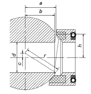
Figure 5 The open state

Figure 6 The closed state
2.1.1 Simple calculation of the eccentric distance of the sphere and the inclination angle of the valve seat
The diameter of the sphere can be preliminarily determined according to the medium's working pressure P and formula (1), and then fine-tuned based on the actual situation, so that the sealing ring can fully fit the spherical surface even if there is a slight angular deviation in the closed state of the sphere, and obtain the sealing. After determining the diameter of the sphere, you can determine the eccentric distance of the sphere and the calculation of the inclination angle of the valve seat. From this structure, it can be seen that the eccentric distance of the sphere and inclination angle of the valve seat are related to each other, and they cooperate with each other to achieve the purpose of easy disassembly and assembly function of the sphere. Therefore, these two factors need to be considered in the actual design. In the formula, r is the radius of the sphere(mm); d is the diameter of the flow channel (mm); bM is the width of the sealing surface (mm).

In order for the sealing ring to seal the sphere, the specific pressure of the sealing ring acting on the sphere is greater than the necessary sealing specific pressure. The calculation of the sealing specific pressure is related to the valve diameter D, medium pressure P, and sealing surface width bM. Therefore, in the calculation process of the specific pressure of the sealing surface, the outer diameter and inner diameter of the sealing ring have been determined, and the dimension of h in Figure 5 can be determined. Assuming that the eccentric distance of the sphere is c, as shown in Figure 5, it can be seen that the value of b can be calculated by equation (2). To make the sphere fit between the two valve seats, the value of c must meet the requirements of equation (3). In the assembly process, the sphere can be easily installed in the valve body in the open state. The sphere rotates 90°. When the valve is closed, the spherical surface can be attached to the sealing surface.

But at this time, the c value has a range. According to this range, a value of c can be determined preliminarily. It is difficult to meet the condition that the ball fits closely with the valve seat’s sealing ring in the closed state due to a certain deviation in actual processing. Secondly, even under ideal conditions, there are almost no processing and assembly errors. After the valve is closed, if you want to achieve a sufficient sealing effect, you still need an initial sealing force to compensate for the insufficient sealing specific pressure when the initial medium pressure is very small. Therefore, an elastic energy storage element needs to be provided for the front valve seat to provide a certain pre-tightening force to the front valve seat to provide the initial sealing force required for the initial sealing. In order to provide the initial sealing force to the valve seat, a certain amount of compression is required for the elastic energy storage element. In order to meet the requirement that the ball can be easily put into the valve body in this case, the condition of formula (4) needs to be met. After the ball is installed in the valve body, rotate the ball when the valve is closed. The ball will squeeze the valve seat to make the elastic energy storage element produce certain compression, forming an initial sealing force, meeting the design requirements and achieving the purpose of sealing.
From formula (4), a limiting condition for the value of a can be obtained. At this time, the size of a is determined according to the needs, that is, the inclination angle of the valve seat is determined.

Given that there are disadvantages for the current common floating ball valve structure, a new type of ultra-low temperature floating ball valve is conceived, so that it can not only meet the required sealing performance, but also realize the online maintenance function, reducing the processing difficulty and meeting the requirements for easy disassembly and assembly.
The structure of the new ultra-low temperature floating ball valve is shown in Figure 4. It is mainly composed of valve bodies, springs, front valve seats, sealing rings, balls, gaskets, extended valve bonnets and valve stems.
Figure 4 The structure of the new ultra-low temperature floating ball valve
1. Valve bodies 2. Springs 3. Front valve seats 4. Sealing rings of valve seats 5. Spheres 6. Rear valve seats 7. Lip rings of valve seats 8. Middle lip rings 9. Gaskets in the middle passage 10. Gasket A 11. Bolts and nuts 12. Extended valve bonnets 13. Valve stems 14. Drip trays 15. Gasket B 16. Lip rings of stems 17. Gasket C 18. Filling 19. Packing glands 20. Positioning plates 21. Handles 22. Nuts
The middle cavity wall of the valve body is a vertical plane perpendicular to the flow channel. Two wedge shaped valve seats are installed on both sides of the middle cavity. One side of the plane contacting two valves and valve bodies is designed as the vertical plane and the other side of place contacting the sphere is designed to have a bevel with a narrow width on the top and a wide width at the bottom. The front valve seat is equipped with a spring on the side close to the valve body to provide initial sealing force for the sealing of the valve seat and the ball. One side of the front and rear valve seats close to the ball is equipped with a sealing ring to seal the space between the valve seat and ball. A lip shaped sealing ring is provided between the valve seat and valve body for sealing.
The bonnet and the valve body are connected by bolts, and the middle seal is composed of two seal structures, a lip seal ring and a metal winding gasket. The seal between the stem and bonnet consists of two sealing structures, a lip seal ring and a packing. The packing gland and the bonnet are connected by bolts. In order to prevent the packing from shrinking and loosening in low-temperature conditions, a disc spring is installed on the packing gland bolts, providing deformation compensation. The upper end of the valve stem is equipped with a handle, which can control the opening and closing of the valve.
2.1 The sealing of the valve seat
The sealing of the valve seat is based on the idea of an eccentric ball and wedged seat structure. The main structure is shown in Figures 5 and 6; the sphere has an eccentric structure, that is, the center line of the flow channel is below the horizontal axis of the sphere. The eccentric distance is c, and one side of the metal seat and seat sealing ring close to the sphere both have bevel structure. During installation, since the upper part of the valve seat is narrower and there is a gap from a to b between the cutting surface of the sphere, no special tooling is required to control the gap between the two valve seats, which is convenient for installing the sphere. When the valve is in the closed state, the ball is tightly attached to the sealing surface of the valve seat under the action of the pre-tightening force of the energy storage device such as the front valve seat spring to achieve the purpose of sealing. Compared with the bevel ball valve structure in Figure 1, this can effectively reduce the opening and closing torque, and is easier to assemble without jamming. In addition, this new type of floating ball valve has fewer parts and is easy to process. While effective sealing performance is ensured, it is particularly convenient to disassemble the new kind of floating ball valve. Quick maintenance and replacement of parts on the pipeline can be realized.
Compared with conventional side entry floating ball valves and top entry floating ball valves, there are two aspects which should be paid attention to in the realization of the new floating ball valve structure: First, the eccentric distance of the sphere is difficult to determine. If the eccentric distance of the sphere is not enough, it will not be easy to disassemble. If the eccentric distance of the ball is too great, it will cause the ball to be separated from the sealing ring when the valve is closed, and it cannot be sealed; the size of the valve seat is too large, resulting in unnecessary material waste. Second, the inclination angle of the valve seat needs to be designed to ensure that the valve is easy to disassemble and assemble when the valve is in the open state, and the ball has a certain squeezing effect on the valve seat in the closed state, providing pre-tightening force for the spring and other energy storage devices.
Figure 5 The open state
Figure 6 The closed state
2.1.1 Simple calculation of the eccentric distance of the sphere and the inclination angle of the valve seat
The diameter of the sphere can be preliminarily determined according to the medium's working pressure P and formula (1), and then fine-tuned based on the actual situation, so that the sealing ring can fully fit the spherical surface even if there is a slight angular deviation in the closed state of the sphere, and obtain the sealing. After determining the diameter of the sphere, you can determine the eccentric distance of the sphere and the calculation of the inclination angle of the valve seat. From this structure, it can be seen that the eccentric distance of the sphere and inclination angle of the valve seat are related to each other, and they cooperate with each other to achieve the purpose of easy disassembly and assembly function of the sphere. Therefore, these two factors need to be considered in the actual design. In the formula, r is the radius of the sphere(mm); d is the diameter of the flow channel (mm); bM is the width of the sealing surface (mm).
In order for the sealing ring to seal the sphere, the specific pressure of the sealing ring acting on the sphere is greater than the necessary sealing specific pressure. The calculation of the sealing specific pressure is related to the valve diameter D, medium pressure P, and sealing surface width bM. Therefore, in the calculation process of the specific pressure of the sealing surface, the outer diameter and inner diameter of the sealing ring have been determined, and the dimension of h in Figure 5 can be determined. Assuming that the eccentric distance of the sphere is c, as shown in Figure 5, it can be seen that the value of b can be calculated by equation (2). To make the sphere fit between the two valve seats, the value of c must meet the requirements of equation (3). In the assembly process, the sphere can be easily installed in the valve body in the open state. The sphere rotates 90°. When the valve is closed, the spherical surface can be attached to the sealing surface.
But at this time, the c value has a range. According to this range, a value of c can be determined preliminarily. It is difficult to meet the condition that the ball fits closely with the valve seat’s sealing ring in the closed state due to a certain deviation in actual processing. Secondly, even under ideal conditions, there are almost no processing and assembly errors. After the valve is closed, if you want to achieve a sufficient sealing effect, you still need an initial sealing force to compensate for the insufficient sealing specific pressure when the initial medium pressure is very small. Therefore, an elastic energy storage element needs to be provided for the front valve seat to provide a certain pre-tightening force to the front valve seat to provide the initial sealing force required for the initial sealing. In order to provide the initial sealing force to the valve seat, a certain amount of compression is required for the elastic energy storage element. In order to meet the requirement that the ball can be easily put into the valve body in this case, the condition of formula (4) needs to be met. After the ball is installed in the valve body, rotate the ball when the valve is closed. The ball will squeeze the valve seat to make the elastic energy storage element produce certain compression, forming an initial sealing force, meeting the design requirements and achieving the purpose of sealing.
From formula (4), a limiting condition for the value of a can be obtained. At this time, the size of a is determined according to the needs, that is, the inclination angle of the valve seat is determined.
