Improvement in Butterfly Check Valves
1. The improvement plan
According to the failure of the butterfly check valve, the structure of the valve disc and the connection between the valve disc and the positioning rod can be improved to eliminate the stress concentration at the connection part, reduce the probability of failure of the butterfly check valve when it is used, and prolong the service life of the check valve. The disc of the butterfly check valve and the connection between the disc and the positioning rod are improved, and the finite element software is used to simulate and analyze; an improved scheme to solve stress concentration is proposed. The structure model of the improved scheme is shown in Figure 1.
(1) Improve the form of the disc. Design grooves on the disc of the check valve to reduce the weight of the disc, thereby changing the force distribution of the disc, and observe the force of the disc and the connection between the disc and the positioning rod. This solution can make the force of the valve disc more uniform, and effectively improve the stress concentration of the butterfly check valve.
(2) Improve the form of the disc, and carry out an arc-shaped thickening design on the back of the check valve disc to improve the strength of the disc, thereby changing the force distribution of the disc, making the force of the disc more uniform, and improving the stress concentration of the butterfly check.
(3) Improve the form of the connection part between the valve disc and the positioning rod; lengthen and thicken the connection part, and increase the contact area between the connection part and the back of the valve disc, thereby improving the stress concentration of the butterfly check valve.
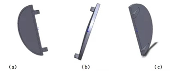
(a) The design groove on the valve disc (b) The arc thickening on the back of the valve (c) The connecting part being lengthened and thickened
Figure 2 The improvement plan
2. Finite Element Analysis
2.1 Before structural optimization
In the opening and closing process of the butterfly check valve, it is impacted by the flowing medium in the pipeline system, and a three-dimensional model is established and numerical simulation and analysis are carried out. The stress distribution of the disc of the butterfly check valve under the impact of the fluid medium is shown in Figure 2. It can be seen in the figure that the place where the disc is most stressed is the red part, almost all of which are located in the connecting part between the disc and the positioning rod; the stress value exceeds 39MPa, and the maximum can reach 217MPa. According to the relevant information, the butterfly check valve is made of alloy steel, and the yield stress is greater than and equal to 216MPa. It can be seen that the maximum stress of the connection part reaches the yield strength of the material, so the valve disc is prone to damage in the opening and closing process.
The cloud diagram of the deformation of the disc of the butterfly check valve under the impact of the fluid medium is shown in Figure 3. It can be seen from the figure that the most severely deformed part of the disc is located at the center of the semicircular disc, which is shown in the cloud diagram. The maximum deformation is about 0.18 to 0.20 mm. In addition, since the two semicircular discs form an integral circular disc, the deformation of the disc is approximately symmetrical to the positioning rod in the middle.
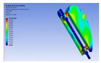
Figure 3 The cloud diagram of stress of the disc of the butterfly check valve
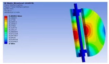
Figure 4 The cloud diagram of the deformation of the disc of the butterfly check valve
2.2 Designing grooves on the surface of the disc
The finite element analysis of the improved check valve disc with grooves on the surface is carried out, and the stress analysis results are shown in Figure 4. It can be seen from Figure 4 that the stress concentration still occurs at the connection between the valve disc and the positioning rod. Comparing the stress distribution of the disc before improvement, the red area representing the maximum stress value is significantly reduced, but the maximum stress value increases from 39MPa before improvement to 161MPa; the stress concentration does not drop but rise, indicating that designing grooves on the surface of the disc cannot solve the problem of excessive stress.
The deformation distribution of the check valve disc with grooves on the surface is shown in Figure 5. Figure 5 shows that the most severely deformed area of the improved valve disc is still at the center of the valve disc, and the color is orange. The deformation cloud picture is also symmetrical on both sides. The maximum deformation of the valve disc is about 0.50 to 0.54 mm, which is nearly doubled compared with before the improvement. The reason is that the designing grooves on the surface of the valve disc cause the thickness to become thinner, so it is more easily deformed after being impacted.
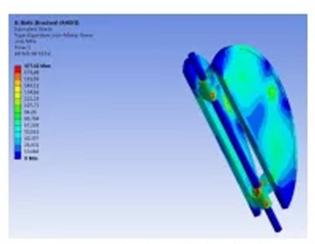
Figure 5 The cloud diagram of the stress of the disc of the butterfly check valve discs with grooves
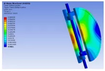
Figure 6 The cloud diagram of the deformation of the disc of the butterfly check valve discs with grooves
2.3 Arc thickening on the back of the disc
The stress distribution after the arc thickening on the back of the disc is shown in Figure 6. The area with the great stress value is still at the connection between the disc and the positioning rod. The maximum stress value is about 79MPa. Compared with the groove on the surface of the disc, the stress concentration is reduced. However, compared with the maximum stress value of 39MPa in the disc structure before the improvement, the structure still cannot be used. The deformation distribution after the arc thickening on the back of the valve disc is shown in Figure 6. The maximum deformation of the valve disc is 0.075 to 0.082mm, and the position with the greatest deformation appears at the edge. This is caused by the arc thickening on the back of the valve disc. Under the same stress, the thinner part of the valve disc edge will deform first, thereby reducing the valve disc’s closing performance.
2.4 Improvement in the connection between the valve disc and the positioning rod
The finite element analysis of the improved check valve disc is carried out, and the stress distribution of the connection part between the disc and the positioning rod is shown in Figure 7. The maximum stress value is 22 to 30MPa, which effectively reduces the stress concentration. By reducing the maximum stress in the stress concentration area, the fatigue wear of the valve disc and the positioning shaft can be reduced, thereby prolonging the service life of the butterfly check valve. The deformation distribution of the connection between the valve disc and the positioning rod is shown in Figure 8. After the connection between the valve disc and the positioning rod is improved, the deformation is symmetrical. The maximum deformation area is located in the middle of the valve disc, and the maximum deformation is 0.13 to 0.15 mm, about 27.8% lower than that before the improvement.
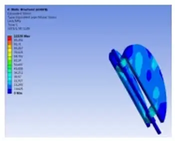
Figure 7 The deformation distribution of the connection part
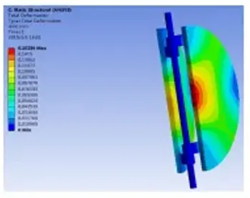
Figure 8 Improvement in the connecting part
3. A comparison of results
The improvement plans are compared, and the analysis data are shown in Table 1. According to the comprehensive analysis of the data in Table 1, it is most reasonable to lengthen and thicken the connection part between the valve disc and the positioning rod, which can not only reduce the stress of the valve disc, but also effectively solve serious deformation to achieve the purpose of reducing the failure probability of the check valve. The most important failure in existing production is solved.
In order to verify the correctness of the improved structure and the simulation analysis results, a butterfly check valve with a longer and thicker connection between the valve disc and the positioning rod was actually produced, and applied to the pipeline system of the circulating water pump station of the ore dressing plant. The test system adopts KQSN 600-M13/631 type water pump. The pumping station is operated by 7 pumps. 4 sets are used and 3 are on standby. The actual outlet pressure of the pumping station is 0.36MPa, and the outlet flow is 11000m3/h. The test results show that the improved check valve can be used for more than 12 months in the same environment and has better performance.
Table 1 A data comparison of the improvement plan
| Structural schemes | Stress/MPa | Deformation/mm | Descriptions |
| Original structure | 39 to 217 | 0.18 to 0.20 | The maximum stress is 217MPa. The disc is made of alloy steel. Yield stress is 2216MPa and the simulation result is greater than the minimum value of the material yield limit. |
| Designing grooves on the surface of the disc | 161 to 477 | 0.50 to 0.54 | The maximum stress increases by 2 to 4 times, and the deformation increases by 3 times. |
| arc-shaped thickening of the back of the disc | 79 to 132 | 0.075 to 0.082 | The maximum stress is reduced by 40%, and the deformation is reduced by 58%, but the deformation is concentrated on the edge of the valve disc, which affects the sealing effect. |
| Lengthening and thickening the connection part between the valve disc and the positioning rod | 22 to 30 | 0.13 to 0.15 | The maximum stress is reduced by about 87%, and the deformation is reduced by 25%. |
4. Conclusion
The transient impact of the flowing medium in the pipeline system on the disc of the butterfly check valve will directly affect the normal operation and service life of the valve. In view of the common faults of the butterfly check valve in actual production, SolidWorks and ANSYS are used to carry out 3D modeling and finite element modeling to improve the working stability of the butterfly check valve and prolong the service life of the butterfly check valve. Comparing the stress and deformation of different improvement schemes, it is determined that the lengthening and thickening of the connection between the valve disc and the positioning rod is the optimal improvement scheme.
